
Electrical Measurement & Monitoring · Selection Guide
Current Transformer Selection Guide: Construction, Ratio, Output and Model Verification
Selecting a current transformer starts with the measurement requirement, not with a model number alone. Buyers should define the physical construction, primary-current requirement, secondary output, ratio, installation fit, accuracy requirement, burden where applicable, frequency, insulation requirements and the exact documentation needed before ordering.
This current transformer selection guide separates general verification steps from published RITOKS product data. It does not calculate a ratio, burden or protection setting, and it does not replace application engineering or the documentation for the exact model.
Current Transformer Selection at a Glance
A useful specification moves from the application requirement to the CT construction and electrical interface, then finishes with physical fit and exact-model documentation. General terminology is described in official technical material from Schneider Electric, its split-core CT installation documentation, and the Socomec current sensor and transformer selection guide. These sources support general concepts only; their ratings and recommendations are not RITOKS product specifications.
Current Transformer Selection Inputs
| Selection input | What to confirm |
|---|---|
| CT construction | Split-core, closed-core or miniature construction required by the installation |
| Primary current requirement | Project current range and the published primary-current option for the exact model |
| Secondary output | Required input for the connected meter or monitoring device |
| Ratio | Published primary-to-secondary relationship for the exact model |
| Conductor / aperture fit | Conductor or busbar dimensions against the published aperture |
| Installation access | Whether the conductor can be disconnected or must remain in place |
| Mounting | Available space, mounting method and lead requirements |
| Frequency | Required operating frequency and exact-model publication |
| Accuracy requirement | Required terminology and the exact published class or performance field |
| Burden | Applicable VA requirement and exact row, where published |
| Insulation / withstand | Project requirement and exact-model documentation |
| Exact model | Complete suffix, variant and orderable configuration |
| Datasheet / documentation | Required electrical, mechanical and compliance documents |
1. Start With the CT Construction
Split-Core Current Transformers
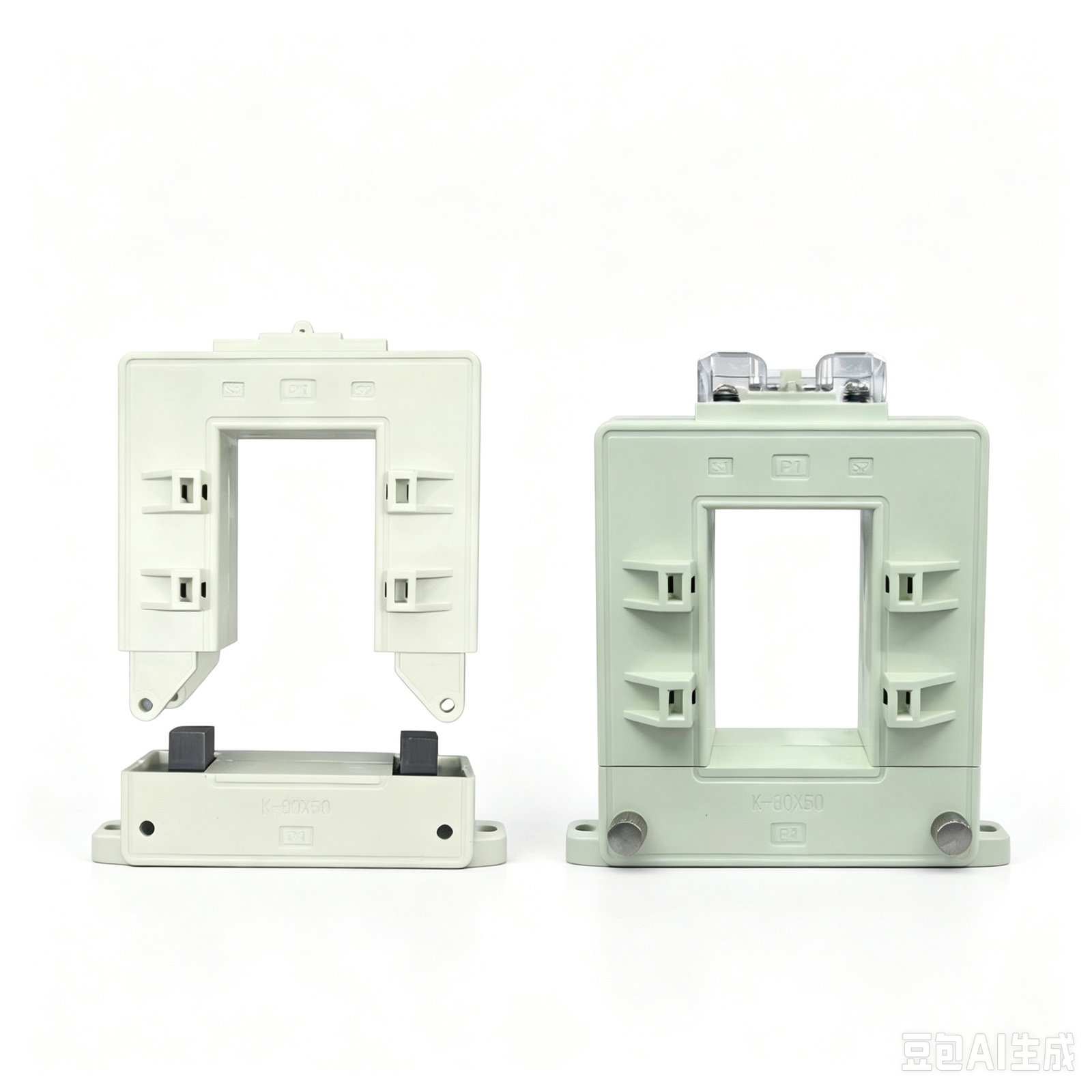
A split-core CT can be opened for installation around an existing conductor or busbar. This can matter where disconnecting the conductor is impractical, but construction alone does not determine the required ratio, output, accuracy or burden. The DP Series split-core current transformer provides a RITOKS construction example across nine published model references. Its complete secondary-output configuration, burden, frequency, insulation, aperture and detailed dimensions are not published and must be confirmed.
Closed-Core Current Transformers
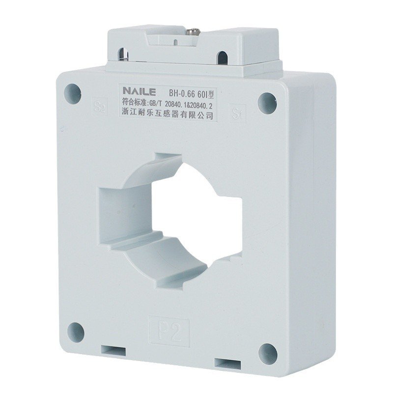
A closed-core CT requires the conductor to pass through its aperture during installation. Buyers should therefore verify installation access as well as electrical specifications. The BH-0.66 60I low-voltage current transformer is a closed-core, one-core family with eleven published /5A ratio rows. Its exact ratio, accuracy class and burden entries must be read together rather than recombined freely.
Miniature Current Transformers
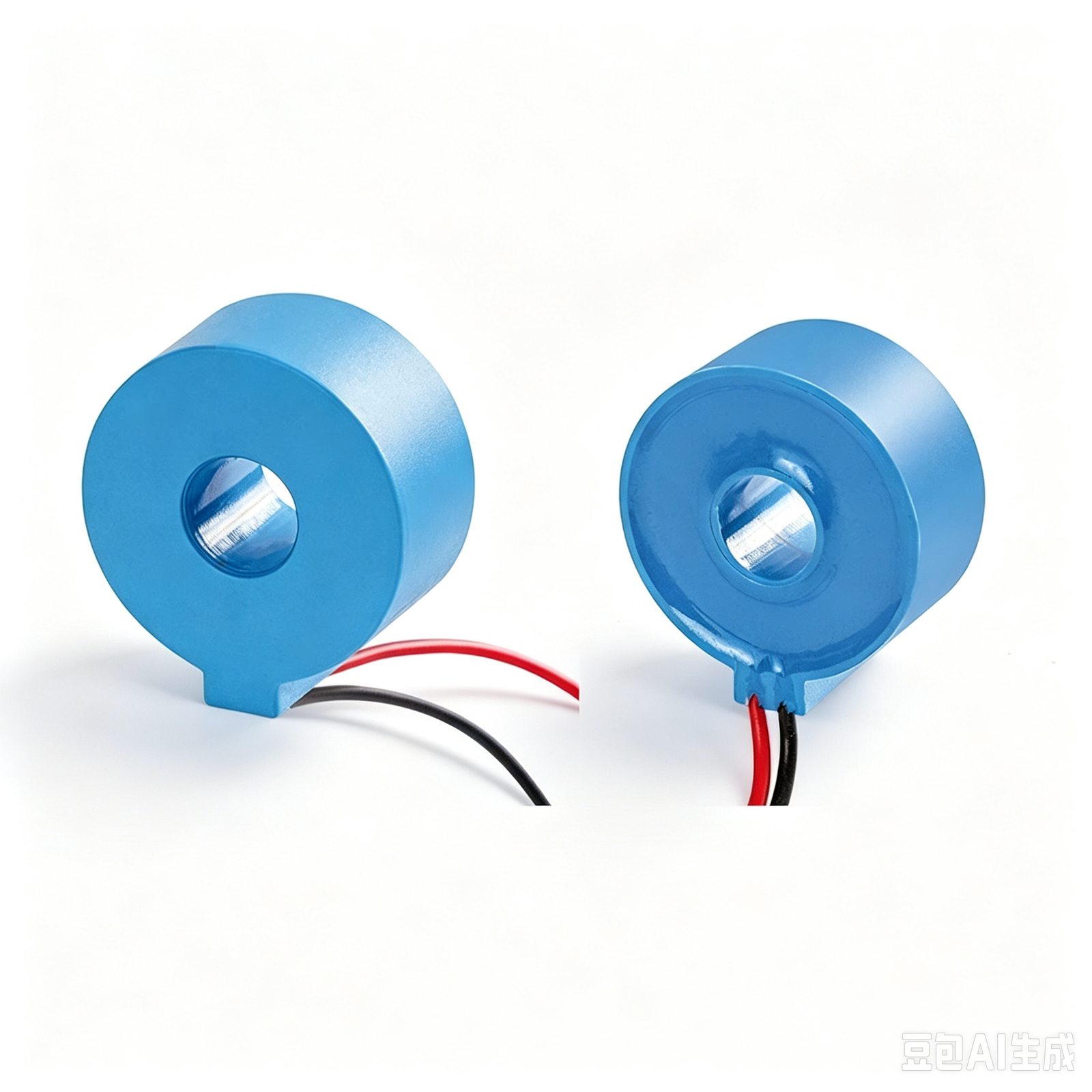
Miniature describes compact physical construction; it is not a claim of superior accuracy or universal suitability. The GTA20L precision miniature current transformer publishes a 26 mm outer diameter, 28.4 mm height, 8.5 mm aperture and 200 mm leads. Those dimensions help with fit verification, while its electrical fields must still be matched to the exact model.
2. Define the Primary Current Requirement
Define the primary-current requirement from the project before screening a family. A published current range shows what a family offers; it does not determine which model the system requires. DP references publish supplier-listed maximum ratio ranges. BH-0.66 60I rows extend from 200/5A through 1500/5A. GTA20L models publish 10–100A AC input. These are different product data structures and should not be treated as interchangeable selection rules.
3. Confirm the Secondary Output and Ratio
A CT ratio describes the relationship between primary current and secondary output for a specified transformer model. First define the primary requirement, identify the secondary output required by the connected measurement device, check an available published ratio, and then confirm the exact model documentation. This sequence avoids assuming that a familiar notation applies across every family.
BH-0.66 60I publishes explicit /5A rows. GTA20L publishes a 20mA AC output and mapped ratios from 500:1 to 5000:1 across its eight models. The DP Series does not publish a complete output configuration for every listed reference. Accordingly, a /5A reference must not be generalized to all RITOKS CTs, and GTA20L must not be presented as a direct substitute for a /5A transformer.
4. Check Aperture and Installation Space
Compare the conductor or busbar dimensions with the CT aperture, then check available space, installation access, mounting method and lead requirements. GTA20L publishes an 8.5 mm aperture and compact body dimensions. Comparable aperture and dimensional fields are not published for the DP Series or BH-0.66 60I on the current pages, so those values require exact-model confirmation. Product images are not dimensional evidence.
5. Verify Accuracy Requirements
Accuracy is a requirement to define and verify, not a simple quality ranking. DP Series pages identify Class 0.5 only where explicitly published. BH-0.66 60I rows include published Classes 1.0, 0.5, 0.5S, 0.2 and 0.2S, but availability depends on the exact row. GTA20L uses published phase-error and linearity terminology rather than the same class table. No class should be selected automatically or used to infer billing, revenue-metering or protection suitability.
6. Check Burden Where It Is Published
Burden is a CT specification that may need to be checked against the connected measurement circuit where it is specified. BH-0.66 60I publishes 2.5VA entries for the 200/5A and 250/5A rows at the displayed Classes 1.0 and 0.5, 5VA entries in exact published rows from 300/5A through 600/5A, and 10VA entries in exact published rows from 750/5A through 1500/5A. These values must remain tied to their source rows. Burden is not published for DP, and the BH VA framing should not be transferred to GTA20L.
7. Confirm Frequency and Insulation Data
Frequency, insulation and withstand requirements should be included when relevant. GTA20L publishes 50/60Hz, insulation resistance greater than 1000MΩ, a 0.66/0.72kV voltage-class field and a 4kV / 50Hz / 1min withstand field. These exact-model fields do not establish corresponding data for DP or BH-0.66 60I, whose current pages do not publish complete frequency and insulation specifications.
Published RITOKS Current Transformer Families
The Current Transformers category sits within Electrical Measurement & Monitoring. The overview below is for family screening only. For adjacent but non-equivalent measurement architectures, compare Rogowski coils such as the ZRC family, Hall current sensors such as the HS2V H02 family, and DC current transducers such as the WBI334U01-S; their sensing principles, outputs and installation requirements are not interchangeable.
Published RITOKS Current Transformer Family Overview
| Family | Construction | Published primary / ratio information | Published secondary output | Accuracy / performance fields | Mechanical data | Key data to confirm |
|---|---|---|---|---|---|---|
| DP Series | Split-core | Nine references with supplier-listed maximum ratio ranges | Complete configuration not published | Class 0.5 only where explicitly published | Not published | Output, burden, frequency, insulation, aperture, dimensions, mounting and documents |
| BH-0.66 60I | Closed-core, low-voltage, one-core | Eleven rows from 200/5A to 1500/5A | 5A in exact published rows | Exact row mappings for class and 2.5VA, 5VA or 10VA entries | Not published | Dimensions, frequency, insulation, mounting and documents |
| GTA20L | Miniature | Eight models; 10–100A AC input; 500:1–5000:1 mapped ratios | 20mA AC | Exact-model phase error, linearity, resistance and linear-range fields | 26 × 28.4 mm body, 8.5 mm aperture, 200 mm leads | Exact model, connected-device compatibility and required documentation |
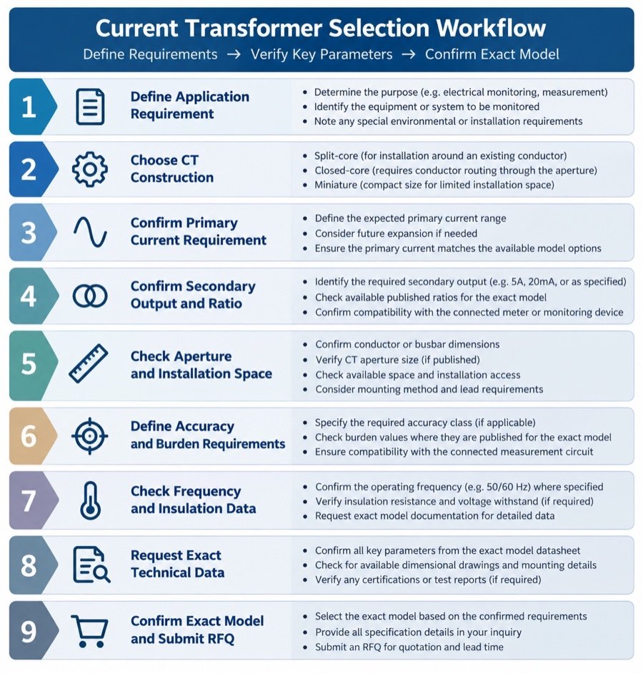
8. Exact-Model Verification Workflow
9. Information to Include in a Current Transformer Inquiry
- Application and measurement requirement
- Required CT construction
- Primary-current requirement
- Required secondary output and ratio, if known
- Conductor or busbar dimensions and required aperture
- Installation access and mounting requirement
- Accuracy and burden requirements, if applicable
- Frequency and insulation or withstand requirements
- Quantity and destination
- Required datasheet, drawing and other documentation
10. What Data Still Requires Exact-Model Confirmation?
Model-level confirmation is essential wherever a page does not publish a complete output configuration, aperture, dimensions, mounting method, burden, frequency, insulation field or supporting document. The absence of a field is not evidence that the requirement is unimportant or that another family’s value applies. Request the exact orderable model and the documentation needed for your project.
Frequently Asked Questions
What information is needed to select a current transformer?
Define the application, construction, primary current, required secondary output, ratio, physical fit, installation access, accuracy, burden where applicable, frequency, insulation requirements and required exact-model documentation.
What is the difference between split-core and closed-core CT construction?
A split-core CT opens around an existing conductor or busbar. A closed-core CT requires the conductor to pass through its aperture. Neither construction alone establishes electrical performance or application suitability.
Can I select a CT from primary current alone?
No. Secondary output, ratio, connected-device compatibility, physical fit, accuracy and other project requirements also need confirmation.
Why must the secondary output and CT ratio be confirmed?
RITOKS families publish different output formats. BH-0.66 60I uses explicit /5A rows, GTA20L publishes 20mA AC output, and the DP Series does not publish every complete output configuration.
Is the same accuracy class available for every RITOKS CT?
No. Accuracy or performance terminology is family- and model-specific. Confirm the exact published row or model documentation.
Are burden values published for every RITOKS current transformer?
No. Exact VA entries are published for specified BH-0.66 60I rows. Burden is not published for the DP Series, and the same framing should not be assumed for GTA20L.
What should I provide when requesting an exact CT model?
Provide the electrical and mechanical requirements, required output and ratio, installation details, quantity, destination and the datasheet or drawings needed for verification.
Confirm the Exact Current Transformer for Your Project
Send RITOKS your application, current, output, ratio, physical-fit and documentation requirements for exact-model review.
Related Resources
Continue exploring Electrical Measurement & Monitoring
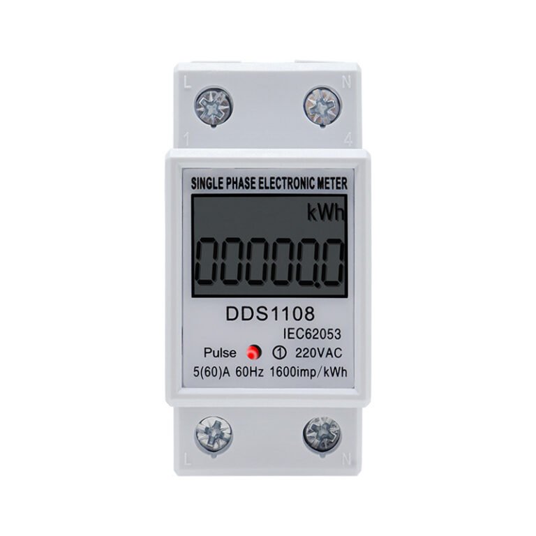
DIN Rail Energy Meter Selection Guide: Phase, Current, Communication and Model Verification
Selecting a DIN rail energy meter starts with the electrical and monitoring requirements, not with a current marking…
Read guide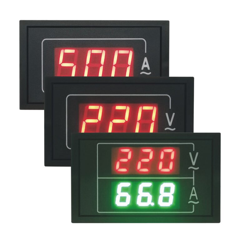
Digital Panel Meter Selection Guide: Function, Range, Panel Cutout and Model Verification
Selecting a digital panel meter begins with the measurement and installation requirements, not with the display appearance alone.…
Read guide