
Technical Resources · Selection Guide
Solid State Relay Selection Guide: Load, Control Input and Thermal Design
Solid state relay selection begins with the load and operating pattern, not with one nominal current value. Output architecture, load voltage, steady and inrush current, control input, switching mode, isolation, ambient conditions, mounting and thermal documentation all affect the exact choice.
This guide provides a sourcing and RFQ workflow. It does not calculate a heat sink, publish a universal derating factor, select protective devices or provide installation wiring.
Solid State Relay Selection at a Glance
OMRON technical guidance separates SSR load type, output element, input circuit, switching behavior and heat dissipation. These general relationships support the selection workflow below; OMRON product ratings are not RITOKS product data.
| Selection input | What to define or verify |
|---|---|
| Load type | Resistive, inductive, motor, lamp, transformer or another documented load behavior. |
| Output architecture | AC or DC output, output element and number of controlled phases. |
| Load voltage/current | Operating range, steady current, minimum load and inrush or surge evidence. |
| Control input | Control voltage/current and interface requirements. |
| Switching mode | Zero-cross or random switching where documented and application-appropriate. |
| Thermal design | Ambient, mounting, spacing, derating curve and heat-dissipation path. |
| Protection | Exact short-circuit, surge and load-fault protection documentation. |
| Documentation | Datasheet, model code, drawing, connection information and required certificates. |
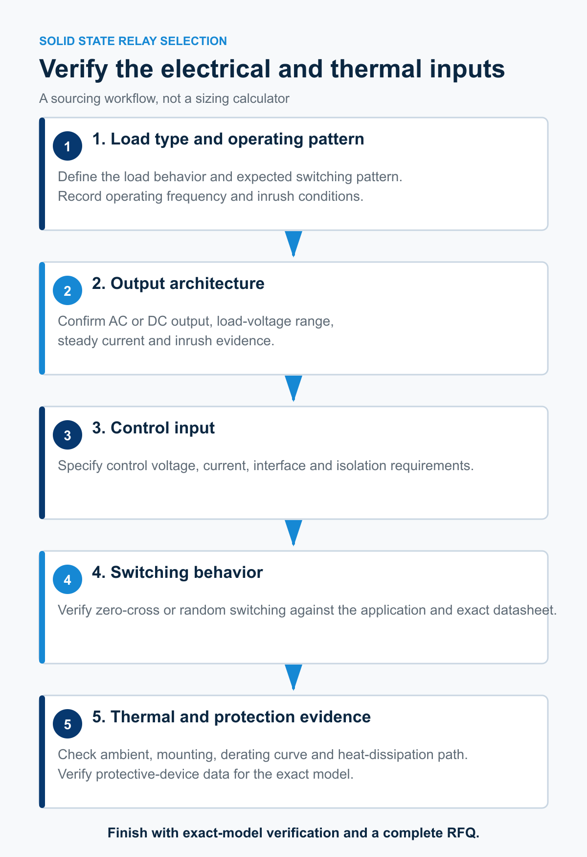
1. Start With the Load and Operating Pattern
Different loads can present different startup or switching behavior. Record the load type, operating voltage, steady current, expected inrush or surge behavior, switching frequency and duty cycle. Do not apply one generic multiplier or current margin to every load.
The exact SSR datasheet must cover the load and operating pattern. If the load behavior is uncertain, request application review instead of selecting from the steady-state current alone.
2. Confirm Output Architecture and Load Ratings
First separate AC-output and DC-output SSRs. Then verify the output element, load-voltage range, load-current range, minimum load and surge-withstand data for the exact model. A PCB-mount AC SSR is not evidence for a panel-mount DC or three-phase SSR.
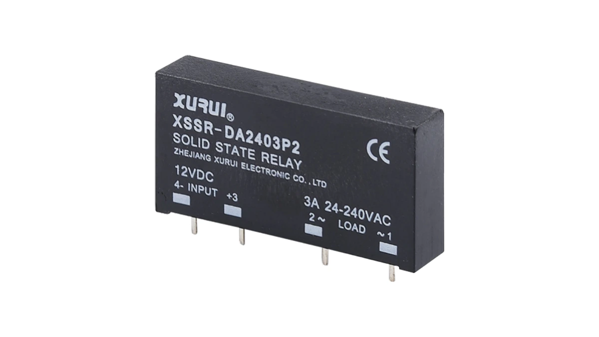
The published XSSR-P2 PCB-mount AC solid state relay is an exact example: it documents AC output, 24-240V AC load voltage and 2A or 3A maximum load-current models. These values are not general SSR selection rules.
3. Match the Control Input and Isolation Requirement
The controller must supply the input voltage and current required by the exact SSR. Confirm the interface, input polarity where applicable and the required isolation evidence. Do not assume every nominal control voltage is available in every output model.
XSSR-P2 documents 5V, 12V and 24V DC control options with 6-30mA control current and opto-electronic isolation. The complete model mapping still comes from its exact ordering documentation.
4. Verify Zero-Cross or Random Switching
For AC-output SSRs, zero-cross and random switching describe different turn-on behavior. OMRON explains that a zero-cross function turns on near the AC voltage zero crossing and can reduce switching noise for suitable loads. Random switching may be required for different control methods. Neither is universally superior.
XSSR-P2 lists zero-cross or random trigger modes as model-dependent. State the application and required control method, then confirm the exact suffix or model.
5. Treat Thermal Design as Model-Specific
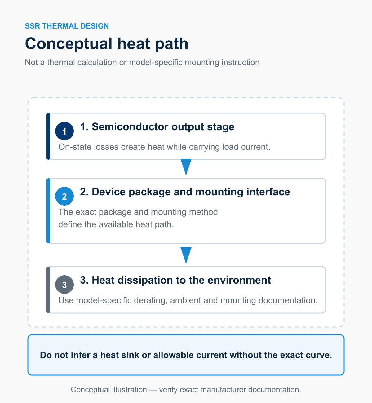
Semiconductor output stages generate heat while carrying load current. The allowable current depends on the exact package, mounting method, ambient temperature, spacing and documented heat-dissipation path. The nameplate current alone is not a thermal design.
Use the exact manufacturer derating curve and mounting instructions. This article does not infer a heat sink, thermal resistance, current reduction or cabinet temperature limit for XSSR-P2 or any other SSR.
6. Confirm Protection and Failure Behavior
SSR output elements can be damaged by load faults, external surges, excessive inrush or overheating. The required fuse, circuit breaker, surge suppression or safety circuit must come from the exact SSR and application documentation.
The related RS95 aR semiconductor fuse is a separate product family. Its presence in the same power-electronics cluster does not establish compatibility with XSSR-P2.
7. Keep SSR and Contactor Selection Distinct
An SSR uses semiconductor switching and has different leakage, thermal and failure considerations from an electromechanical contactor. A contactor uses a coil and mechanical contacts and has different duty and endurance evidence. The AC Contactor Selection Guide should be used when that architecture is under consideration.
The existing SCR Thyristor Module Selection Guide also covers a different product form. Do not treat a discrete power module and a finished SSR as the same selection object.
Published RITOKS XSSR-P2 Example
| Published field | XSSR-P2 evidence | Selection use |
|---|---|---|
| Models | XSSR-2402P2 / XSSR-2403P2 | Confirm the exact model. |
| Output | AC, bidirectional thyristor, normally open | Do not apply to DC-output SSRs. |
| Load voltage | 24-240V AC | Keep the stated AC range. |
| Maximum load current | 2A / 3A by model | Do not use without thermal and load review. |
| Minimum load current | 0.03A | Keep tied to the exact family. |
| Control options | 5 / 12 / 24V DC; 6-30mA | Confirm the exact input version. |
| Trigger mode | Zero-cross or random, model-dependent | Confirm the required model suffix. |
| Mounting | PCB through-hole, dual-row | Not a panel-mount SSR example. |
Browse the Solid State Relays category for the currently published family.
Information to Include in an SSR RFQ
- Load type and operating pattern
- AC or DC output requirement
- Load voltage, steady current and inrush/surge data
- Control input voltage, current and interface
- Required zero-cross or random switching behavior
- Switching frequency and duty cycle
- Ambient temperature, mounting, spacing and enclosure conditions
- Required derating and thermal documentation
- Required protective-device and safety-circuit evidence
- Exact model, drawing, connection information and certificates
- Quantity and destination
Technical References
- OMRON — Technical Explanation for Solid-state Relays — Supports SSR input/output concepts, switching behavior and model-specific thermal considerations.
- OMRON — Solid-state Relay Common Precautions — Supports reviewing load type, inrush behavior, protection and thermal conditions against exact documentation.
- OMRON — Load Current and Ambient Temperature for Solid-state Relays — Supports treating load-current capability as dependent on ambient and mounting conditions.
Frequently Asked Questions
Can I select an SSR from the steady load current alone?
No. Load type, inrush or surge behavior, switching pattern, thermal conditions, control input and exact derating data also require review.
Is zero-cross switching always the correct choice?
No. Zero-cross and random switching suit different control requirements. Use the exact application and model documentation.
Does every SSR require a heat sink?
Do not infer a heat sink requirement from the term SSR alone. Use the exact package, current, ambient, mounting and derating documentation.
Can XSSR-P2 data be used for a panel-mount SSR?
No. XSSR-P2 is a PCB through-hole AC-output family. Other package and output architectures require their own evidence.
Can RS95 be specified as the protective fuse for XSSR-P2?
No pairing is claimed without exact protection and coordination evidence for the selected SSR and circuit.
Confirm a Solid State Relay Configuration
Send RITOKS the load behavior, output and control requirements, switching mode, thermal conditions, protection evidence needs, quantity and destination for exact-model review.