
Technical Resources · Comparison
Solid State Relay vs Contactor: Switching, Isolation and Thermal Differences
A solid state relay and an electromagnetic contactor can both switch a load, but their operating principles, heat path, off-state behavior, isolation evidence and failure considerations differ. The buyer should define the load and switching duty before comparing device size or headline current.
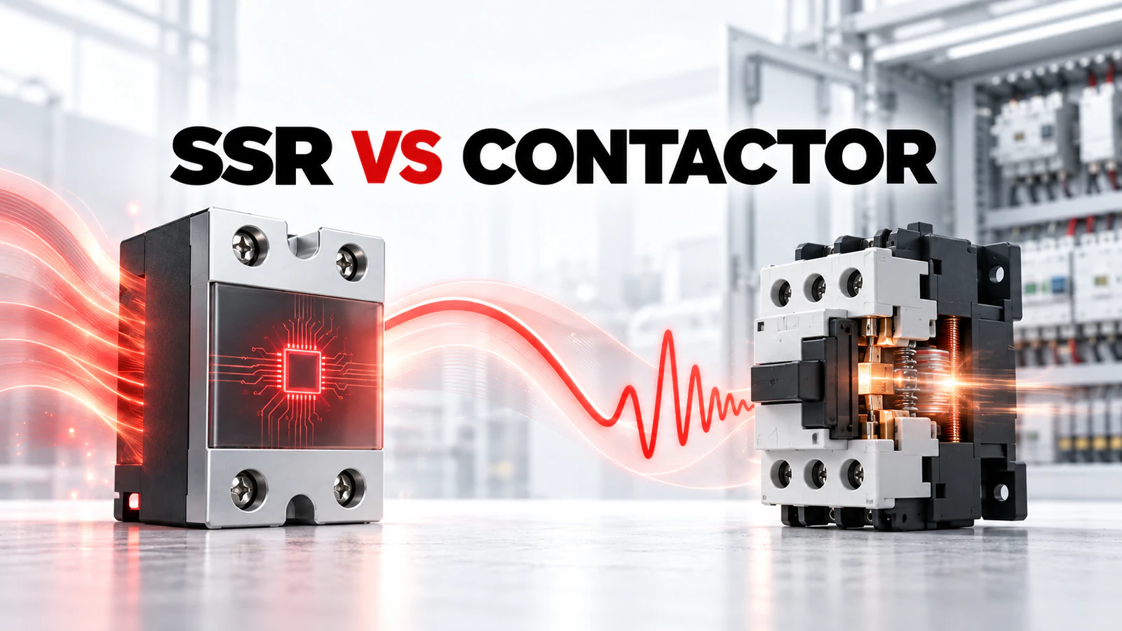
This comparison explains decision inputs. It does not claim that an SSR is a drop-in replacement for a contactor, prescribe a safety circuit or transfer XSSR-P2 specifications to another SSR form.
Buying Decision at a Glance
| Decision input | Buyer must confirm | Evidence required |
|---|---|---|
| Load | AC/DC type, voltage, current and inrush | Exact output/load rating |
| Switching duty | Frequency, timing and required life | Documented operating mode |
| Thermal path | Loss, ambient, mounting and cooling | Derating and thermal data |
| Off-state behavior | Leakage, isolation and safe disconnection needs | Exact datasheet values and system design |
| Failure strategy | Required safe state and external protection | Documented protective measures |
Start With the Load and Switching Pattern
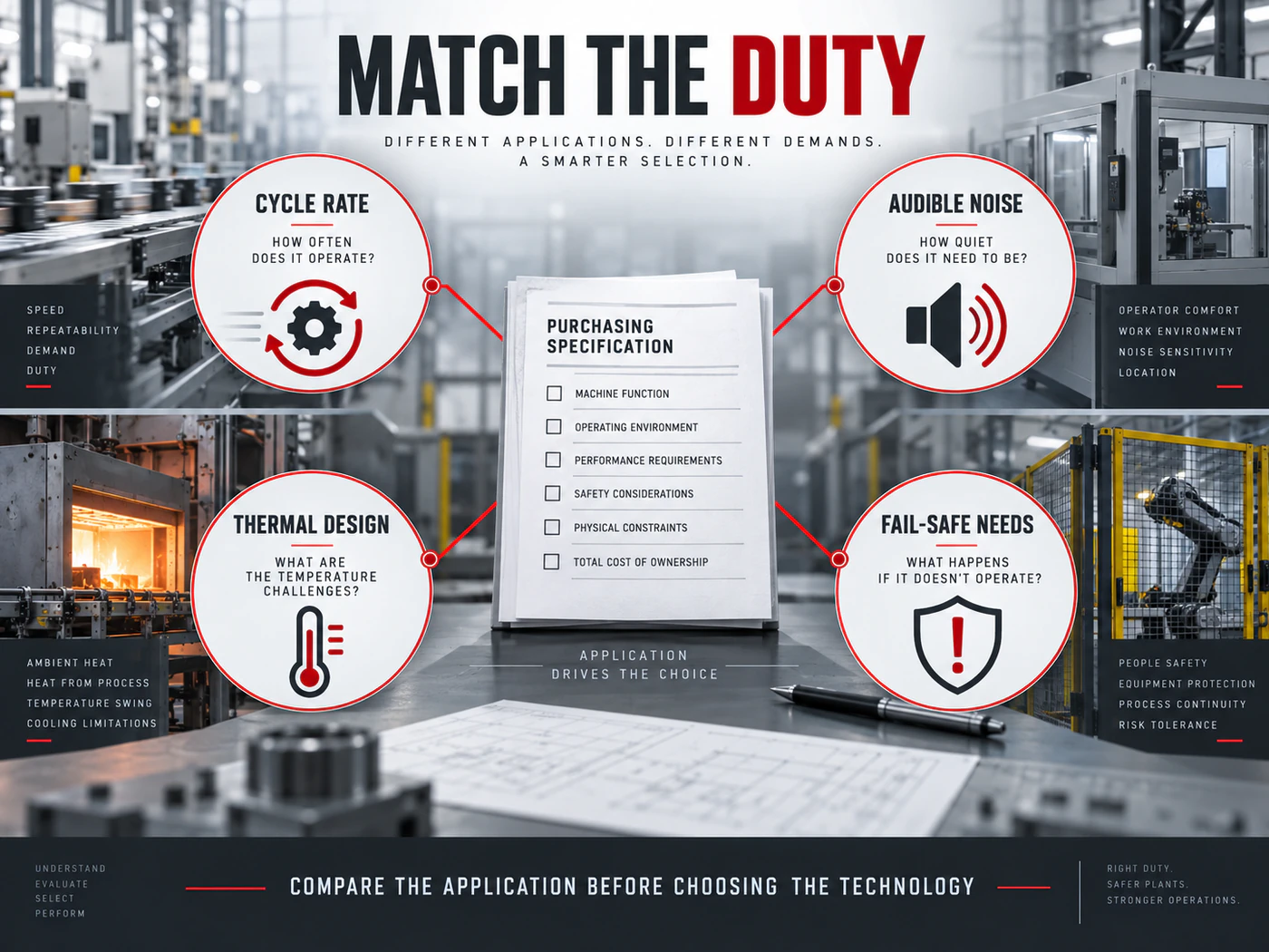
Record whether the load is resistive, inductive, capacitive, motor-related or another documented type. Add supply type, voltage, steady current, inrush and switching frequency. These inputs can disqualify a device even when its nominal current looks adequate.
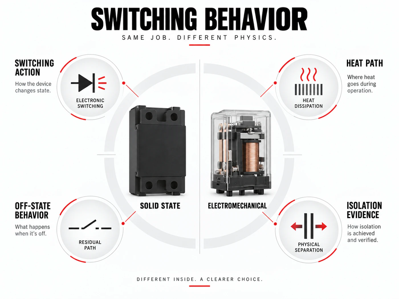
A contactor uses mechanical contacts and a coil. An SSR uses semiconductor output elements. The technologies therefore cannot be compared on current alone. Ask how the exact device behaves during turn-on, turn-off and abnormal conditions.
Account for Heat in the SSR Path
An SSR produces heat while conducting because its output element has a voltage drop or resistance. The exact loss and allowable load depend on the model, current, ambient, mounting and heat path. OMRON guidance treats thermal resistance, heat-sink choice and panel conditions as model-specific engineering inputs.
Do not select a heat sink from the SSR case size. Request the candidate loss data, junction or case limits, required thermal interface and derating curves. A contactor has different thermal and wear considerations, so its enclosure and duty still need review even though the same heat-sink calculation does not apply.
Compare Switching and Off-State Behavior
SSRs can support frequent electronic switching without mechanical contact wear, but the exact trigger mode, response, leakage and surge capability matter. A contactor provides a mechanical contact gap when open, but its utilization category and operating frequency determine suitability and life.
If the process requires visible isolation, fail-safe disconnection or maintenance lockout, define that requirement explicitly. OMRON precautions note that semiconductor devices can fail short and recommend system-level measures; this is a safety-design boundary, not a wiring prescription for RITOKS equipment.
Compare Evidence, Not Technology Slogans
Avoid broad claims such as SSRs are always faster or contactors are always safer. The decision depends on the load, duty, environment, maintenance strategy and exact data. Compare switching frequency, heat removal, noise, leakage, isolation, service access and failure response.
The published XSSR-P2 is a PCB-mount AC-output family with its own control and load records. The ZS3TF is an AC contactor family with utilization-duty data. Neither page proves interchangeability, equivalent isolation or a shared installation.
Build an Evidence File Before Approval
Create one review sheet for the proposed Solid State Relay order code. Put the application inputs in the left column and the supplier evidence in the right column. At minimum, preserve the records for load, switching duty, thermal path and off-state behavior and failure strategy. This makes it clear which information comes from the project and which statement comes from the manufacturer.
Attach the exact datasheet pages, drawings and tables used in the decision. Record their revision or retrieval date and highlight the row for the quoted model. A sales email can clarify scope, but it should not silently replace a technical document when the decision depends on a rating, connection, trip characteristic, thermal limit or tested combination.
Check that every linked value describes the same orderable configuration. Similar model names often share a housing while differing in control supply, current band, poles, terminals, accessories or environmental limits. If a document covers several variants, mark the selected row rather than treating the broadest range on the page as the capability of every variant.
Control Changes During Sourcing
Keep the application record frozen while suppliers prepare quotations. If voltage, load, duty, fault level, enclosure or operating method changes, issue a revised record and ask each supplier to reconfirm the candidate. Otherwise procurement may compare responses that were prepared for different requirements even though the email subject and product family are unchanged.
Apply the same rule to substitutions. A replacement proposed because of price or availability returns to the technical gate with its own order code and evidence. Do not approve it solely because the nominal current, product shape or mounting method resembles the original candidate. The substitution is complete only when the required functions and conditions are rechecked.
Common Procurement Errors
- Selecting Solid State Relay from one headline rating while leaving the application context undefined.
- Using a diagram, curve or accessory table from a neighboring model without confirming scope.
- Treating a product-category page or marketing image as exact-model evidence.
- Comparing a device-only quotation with an assembled or accessory-inclusive quotation.
- Allowing an unresolved technical field to disappear when the commercial offer is revised.
Resolve these errors before commercial comparison. The technical reviewer should be able to trace each accepted statement to the project record or to the exact candidate document without relying on memory. Procurement can then compare price, quantity, destination and lead time against a stable technical baseline instead of reopening the selection after order placement.
How to Compare Supplier Offers
Compare every Solid State Relay offer against one frozen application record. Do not combine the best figures from several variants or accept a family maximum as the rating of the quoted order code. Keep the document revision, test conditions and unresolved fields beside each value so procurement can see whether two offers are genuinely equivalent.
| Comparison point | Required evidence | Do not accept |
|---|---|---|
| Operating element | Semiconductor output | Mechanical main contacts |
| Frequent switching | Check exact SSR duty and thermal data | Check utilization category and operations data |
| Conducting loss | Requires explicit heat-path review | Different coil/contact heating record |
| Open state | Check leakage and failure behavior | Check isolation/contact-gap documentation |
| Replacement decision | Not drop-in by default | Not drop-in by default |
A quotation can remain commercially interesting while technically incomplete. Mark missing data as an open action and ask the supplier for the exact page, drawing or combination table. Price and lead time should be compared only after the technical scope is normalized. This prevents a lower-cost but narrower offer from appearing equivalent to a complete documented solution.
Decision Workflow
- Define load type, voltage, steady current and inrush.
- Record switching frequency and control signal.
- State isolation, safe-state and maintenance requirements.
- Compare SSR thermal data with contactor duty/life data.
- Review surge, short-circuit and external protection responsibilities.
- Select only from exact manufacturer documentation.
At each step, preserve the boundary between project inputs and supplier evidence. The project team defines the application and required functions; the supplier identifies an exact product and provides its documents. Neither side should fill an evidence gap by inference from appearance, a nearby model or a shared headline rating.
RFQ Preparation Checklist
A useful RFQ for solid state relay vs contactor should be concise enough to answer but complete enough to prevent silent assumptions. Attach the available project record and identify unknown values as questions. Ask the supplier to answer with an exact orderable code rather than a generic product-family recommendation.
- Load type and supply
- Steady current and inrush evidence
- Switching frequency and control input
- Ambient, mounting and cooling context
- Off-state and isolation requirements
- Failure-response and protection requirements
- Quantity and destination
Request the current datasheet revision and identify the scope of any certification, coordination or compatibility claim. If the response proposes a substitute, require the same evidence set for that substitute. Record quantity and destination after the technical inputs so commercial terms do not obscure unresolved engineering questions.
Stop Conditions Before Order Release
Do not release the order while a publication-critical input is unknown, the quoted model is ambiguous, or a required rating is supported only by another manufacturer’s document. Stop as well when a combination claim lacks exact component codes or when a diagram is being reused across product families. These are evidence gaps, not editorial details.
The final approval record should state what the selected item does, what remains outside its scope and which exact documents support the decision. If the application, duty, environment or proposed model changes, reopen the relevant checks rather than carrying the previous conclusion forward.
Frequently Asked Questions
Is an SSR always a direct replacement for a contactor?
No. Control, load, heat, leakage, isolation and failure behavior all require review.
Why does an SSR need thermal data?
Its semiconductor output dissipates heat during conduction; exact loss and heat-path limits control usable current.
Which device is better for frequent switching?
There is no universal answer. Compare exact SSR thermal/switching data with the contactor utilization category and endurance record.
Related RITOKS Products and Guidance
Use these links as separate category, product and educational records. A contextual link does not claim interchangeability, compatibility or a coordinated combination.
Solid State Relay product category
Solid state relay selection guide
Technical References
The following authoritative sources support only the general concepts stated below. Their product values, diagrams, combinations and approvals do not transfer to RITOKS products.
OMRON, Further Information of Solid-state Relays
Supports SSR switching and thermal-design concepts, including the use of exact loss and thermal-resistance data. OMRON values apply only to its cited models.
OMRON, Solid-state Relay Safety Precautions
Supports the need to evaluate heat dissipation, ambient conditions and fail-safe protection from exact documentation. It is not installation approval for RITOKS products.
Schneider Electric, TeSys Giga Utilization Categories
Defines AC-3 and AC-4 by load and operating duty. It does not establish a RITOKS model rating.
Request an Exact-Model Review
Send the recorded application requirements, exact documentation questions, quantity and destination through the RITOKS contact form. An RFQ requests an exact-model review; this guide does not approve a wiring design, installation or automatic substitute.